Manage Inspection Points
- 21 Dec 2022
- 9 Minutes to read
- Print
- DarkLight
- PDF
Manage Inspection Points
- Updated on 21 Dec 2022
- 9 Minutes to read
- Print
- DarkLight
- PDF
Article Summary
Share feedback
Thanks for sharing your feedback!
Inspection Point Overview
When you deploy your Model, that Model is introduced to new images taken by a camera in your workspace. Some examples include cameras on production lines, cameras on street lights, cameras on cars, or even cameras on mobile devices. You can create Inspection Points in LandingEdge to connect your camera to the application. This will allow you to monitor your camera's images in LandingEdge.
Notes:
- Only one Model can be deployed to a single Inspection Point.
- You can have multiple Inspection Points based on your computer's memory limitations.
Create Inspection Points
- Click Add Inspection Point.
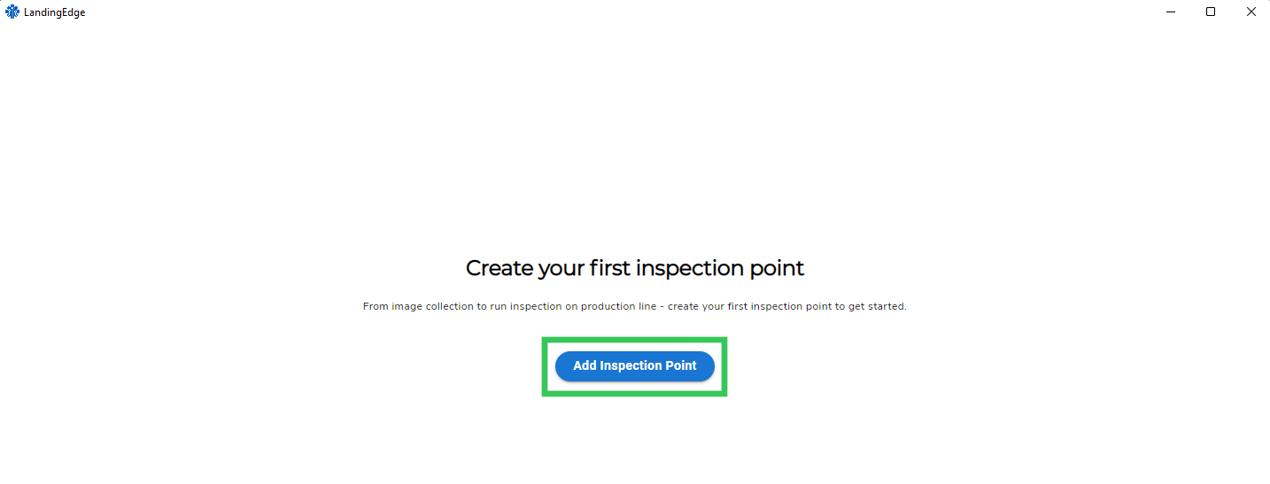 Add Inspection Point
 - Enter a short, descriptive name for the Inspection Point in the Inspection Point Name field.
- Click Add Inspection Point.
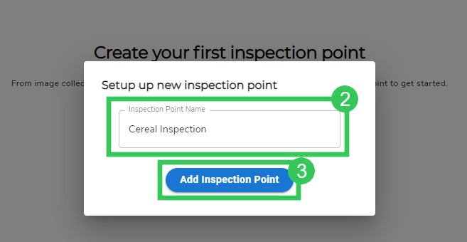 Add Inspection Point Name and Create the Inspection Point
 - Configure the Inspection Point settings accordingly.
- Click Save Configuration.
.png) Save Configuration
Save Configuration


.png)
Inspection Point Settings
This section describes the Inspection Point settings.
Media Source
Caution:
Only one GenTL producer should be installed. If you have multiple GenTL producers installed, LandingEdge may not be able to detect your camera.
Select where you want LandingEdge to look for images from the Media Source drop-down menu:
- Input Folder: Select a folder. LandingEdge will continuously look for new images added to this folder.
.png) Input Folder
Input Folder - Webcam: Select a webcam. LandingEdge will collect images from the selected webcam or USB camera. If you have multiple webcams connected to your computer, LandingEdge will automatically pick a webcam.
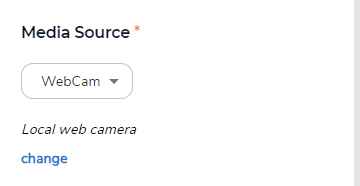 Webcam
 - GenICam: LandingEdge will connect to your GenICam standard camera. (LandingEdge does not support smart cameras.) To connect your GenICam standard camera, you must first download and install a compatible GenTL producer. If you do not have one from your camera's manufacturer, it is recommended to installMatrix Vision mvGenTL_Acquire.
- Web API: Enter any number from 7,000 to 8,000. This will be your port number for your API. LandingEdge will monitor this port number to receive images from your API call.
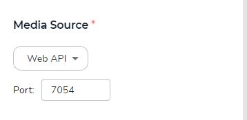 Web API
.png)


Note:
If you select a GenICam or webcam, that camera can only be used for one active Inspection Point at a time.
Preview Settings
The Preview settings display after you have configured your Media Source. They are only applicable to GenICam cameras or webcams. These are the settings:
- View Live: See a live feed of your camera's view. This is useful to check if the camera is in focus or facing the right direction, for example.
- Grab a Frame: Take a picture using the connected camera. This option does not work in View Live. This will run inference if you have a model loaded.
- Save to Disk Automatically: Automatically save images captured by the Grab a Frame setting. (This setting will not save images from View Live.)
.png) Preview Settings
Preview Settings
.png)
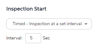
Inspection Start
Select how often you want the camera to capture images from the Inspection Start drop-down menu:
- Timed: Set the timed interval (in seconds) in which the camera will take a picture.
- PLC: Configure your Programmatic Logic Controller (PLC) to determine how often you want the camera to take a picture.
 Inspection Start

Note:
The Inspection Start setting is only applicable to GenICam cameras or webcams.
Cloud Connection
You can establish a connection between LandingEdge and LandingLens by entering your API credentials in the Cloud Connection section.
 Enter API Credentials to Connect to LandingLens
This will allow you to connect a LandingLens Project to your Inspection Point.
 Select a LandingLens Project
Generate API Credentials
Caution:
If you already have an API Key or API Secret generated, creating a new one will replace those credentials and interrupt any connected services. Ensure that you do not have these API credentials already before making new ones.
To generate your API credentials:
- Log in to LandingLens.
- Click the User Menu and select API Key.
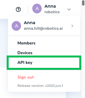 API Key in the User Menu
 - Click Generate API Key.Caution:If you already have an API Key or API Secret generated, creating a new one will replace those credentials and interrupt any connected services. Ensure that you do not have these API credentials already before making new ones.
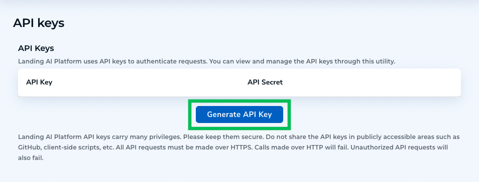 Generate API Key
 - A pop-up window displays the API Key and Secret credentials. Save these credentials.
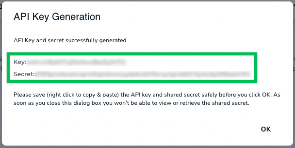 Save the API Key and Secret in a Safe Location Before Closing the Window
 - Click OK to close the window. You can now connect a LandingLens Model to your Inspection Point.Caution:
After you close the pop-up window, you will no longer be able to retrieve the API Secret again. Ensure that you have saved it in a safe location before closing the window.


Model
Select how you want to load your Model from the Model drop-down menu:
- If you used the Run Live feature to download a Model Bundle, you can select that Model Bundle. This option only works if you have also saved your API credentials to the Cloud Connection setting.
 You Can Select a Downloaded Model Bundle
 - If you saved your API credentials to the Cloud Connection setting, you can select a Model from LandingLens for online use.
- If you did not save your API credentials, you must download your Model from LandingLens, then load it in the Model setting in LandingEdge.

Note:
You must have a Deployment License before you can select a LandingLens Model.
 Model Loaded to the "Model" Setting
 Select LandingLens Models for Online Use
The procedure in this section describes how to download a LandingLens Project and load it in LandingEdge. Follow this procedure if you entered your API credentials in the Cloud Connection setting and have a connection to LandingLens.
To download a LandingLens Project and load it in LandingEdge:
- Open LandingLens.
- Open the Project you want to download.
- Train your Model.
- After you have trained your Model and you have the results that you want, save your Model:
- Click Save Model. A pop-up window displays.
.png) Save Model
Save Model - Enter a brief, descriptive name for your Model in the Name Your Model field.
- Enter a description for your Model in the Describe Your Model field.
- When you train a Model, the images you provide are split into different sets. Select the set you want to run error analysis on from the Run Error Analysis On drop-down menu.
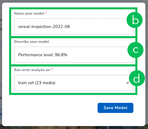 Configure the Model Details
 - Click Save Model.
- Click Save Model. A pop-up window displays.
- Click Models in the left side panel. The saved Models display.
- Click the bottom vertical ellipsis icon and select Add to Deployment.
.png) Add to Deployment
Add to Deployment - Click Deployment in the left side panel.
- In the Models tile, click View & Deploy. All available Models to deploy display.
- Click Deploy on the Model you want to deploy.
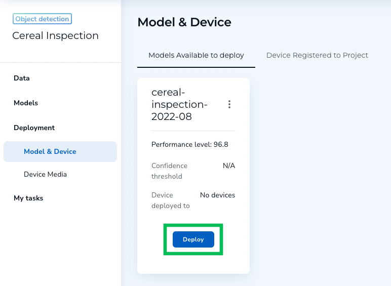 Deploy
 - Open LandingEdge.
- Select the LandingLens Model you want to deploy from the Model setting.
.png)

.png)

Download LandingLens Model for Offline Use
The procedure in this section describes how to download a LandingLens Model and load it in LandingEdge. Follow this procedure if you did not enter API credentials in the Cloud Connection setting and are not connected to LandingLens.
To download a LandingLens Model and load it in LandingEdge while offline:
- Open LandingLens.
- Open the Project you want to download.
- Train your Model.
- After you have trained your Model, and you have the results that you want, save your Model:
- Click Save Model. A pop-up window displays.Save Model
- Enter a brief, descriptive name for your Model in the Name Your Model field.
- Enter a description for your Model in the Describe Your Model field.
- When you train a Model, the images you provide are split into different sets. Select the set you want to run error analysis on from the Run Error Analysis On drop-down menu.Configure the Model Details
- Click Save Model.
- Click Save Model. A pop-up window displays.
- Click Models in the left side panel. The saved Models display.
- Click the bottom vertical ellipsis icon and select Add to Deployment.Add to Deployment
- Click Deployment in the left side panel.
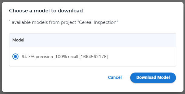
- In the Models tile, click View & Deploy. Allavailable Models to deploy display.
- On the Model you want to download, click the vertical ellipsis icon and select Download.
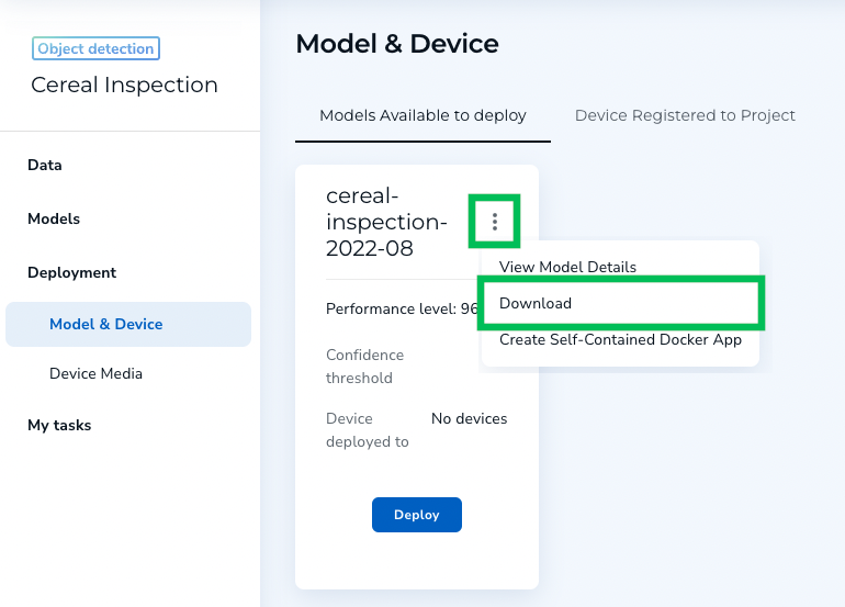 Download
 - Open LandingEdge.
- Open the Inspection Point you want to load your Model to.
- In the Model setting, click Select.
- Select the downloaded LandingLens Model you want to deploy.

Communication
LandingEdge is currently only compatible with Rockwell CompactLogix and ControlLogixPLCs. You can connect your Rockwell PLC from the Communication setting. This will allow you to have more granular control over when your Inspection Point should take images.
 Communication
To connect your Rockwell PLC:
- Select Rockwell from the PLC Type drop-down menu.
- Enter the IP address and slot number of the PLC in the Address field. Your entry must be in this format: [IP Address]/[Slot Number]. Example: 192.168.1.5/0.
- Configure the Input and Output settings accordingly by entering the PLC Tag in the provided fields. Your connected camera will take images according to the settings applied here. For example, say you want to take an image whenever a part you want to inspect is properly positioned by a robot. You can use the inputs and outputs to do that.
- Click Set Inputs & Outputs to save your configuration.
Inputs
Notes:
- True (or High) indicates that the value is on.
- False (or Low) indicates that the value is off.
The table below describes the configurable inputs:
| Input | Description |
|---|---|
| Trigger | This input coincides with the Trigger Ready output. Takes images immediately when the Trigger goes from Low to High (False to True). |
| Results Ack | You should configure the PLC to set this setting to High (True) to indicate results and errors from LandingEdge have been received so result output can be reset for the next result. |
Outputs
The table below describes the configurable outputs:
| Output | Description |
|---|---|
| Trigger Ready | Indicates LandingEdge is ready to receive the trigger to capture and process an image. |
| Results Ready | Indicates inference is complete and results are ready on the output signals to be read by the PLC. |
| Results OK | Indicates the image is good. Note: This is the default result if you run a Classification Model. |
| Results NG | Indicates that the image is not good. |
| Classification | This option is only for Classification Models. Indicates the predicted Class ID. |
| Error | Indicates that an error has occurred during processing. The results will not be sent. |
| Online/Ready | Indicates LandingEdge is running. |
| Heartbeat | Checks to make sure the connection from LandingEdge to the camera is still available. LandingEdge performs this check every five seconds by default. |
| Busy | Indicates LandingEdgeis processing. |
Example Setup of LandingEdge and a PLC
You can configure your PLC to have more granular control over when images will be taken. To assist with this process, LandingEdge offers several Input and Output settings to help keep your PLC connection synchronized and in control.
The cycle described in this section is an example of how LandingEdge and your PLC can work together by configuring the Input and Output settings.
Notes:
- "True" (or "High") indicates that the value is on.
- "False" (or "Low") indicates that the value is off.
- LandingEdge indicates that it is Online.
- LandingEdge is ready and asserts Trigger Ready (True).
- The PLC asserts Trigger (True) based on the set configurations. LandingEdge receives this signal and recognizes that it is time to take an image.
- LandingEdge changes Trigger Ready to False. The PLC receives this signal and recognizes that LandingEdge acknowledged the Trigger.
- LandingEdge asserts Busy (True) to indicate that it cannot be triggered again. The PLC can monitor this signal.
- After LandingEdge has received and processed an image, Result OK and Result NG are set to True or False accordingly.
- Classification will be set if you are running a Classification Model.
- If an error occurs, Error will be set to True.
- After the Results are set, LandingEdge asserts Results Ready (True) to indicate results are available for the PLC to read.
- The PLC recognizes that Results Ready or Error is set to True. It will read the appropriate values—like Result OK, Result NG, and Classification—to determine the final prediction from the AI.
- After the PLC reads the results, it asserts Results Ack. LandingEdge receives this signal and recognizes that the PLC read the results and the cycle is complete.
- LandingEdge resets the result signals and is ready to initiate the cycle again (starting from step 2).
Media Saving
You can save all images captured from LandingEdge or none from the Media Saving setting. To do this:
- Select whether you want images to be saved from the drop-down menu.
- If you choose to save all images, click Change and select the folder you want to save images to.
- If you want to run continuous learning, you can select the Upload Results to LandingLens checkbox. This will automatically the saved images to LandingLens. You can then label these images and retrain your Model.
.png) Media Saving
Media Saving
.png)
Other Settings
You can choose to start running the Inspection Point each time your Windows computer starts up by selecting the Start Running Automatically when LandingEdge Starts checkbox.
 Other Settings
Save Configuration / Run Now
After you have configured your Inspection Point, click Save Configuration to save your changes.
You can click Run Now to start automatically running inference. (You must Save your Inspection Point before you can run inference.)
Was this article helpful?